
After 6 months of driving with a manual pushbutton left turn signal, I decided it was finally time to build a more permanent solution. In the 2013 Volkswagen Passat, the turn signals always have at least a 33% duty cycle of 12 V powering them, giving a dull glow. Then when the brakes are pressed or turning is indicated, the turn signals go to 100% duty cycle.
- Add an in-car monitor to observe the lighting behavior while driving
- Wire up a quick-connect to easily swap devices
- Build and program the “Turn signal Arduino device”
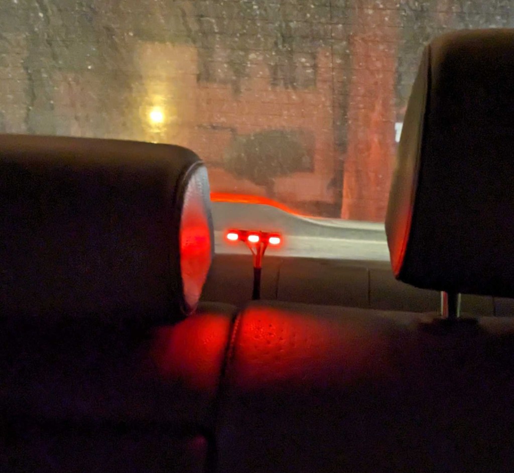
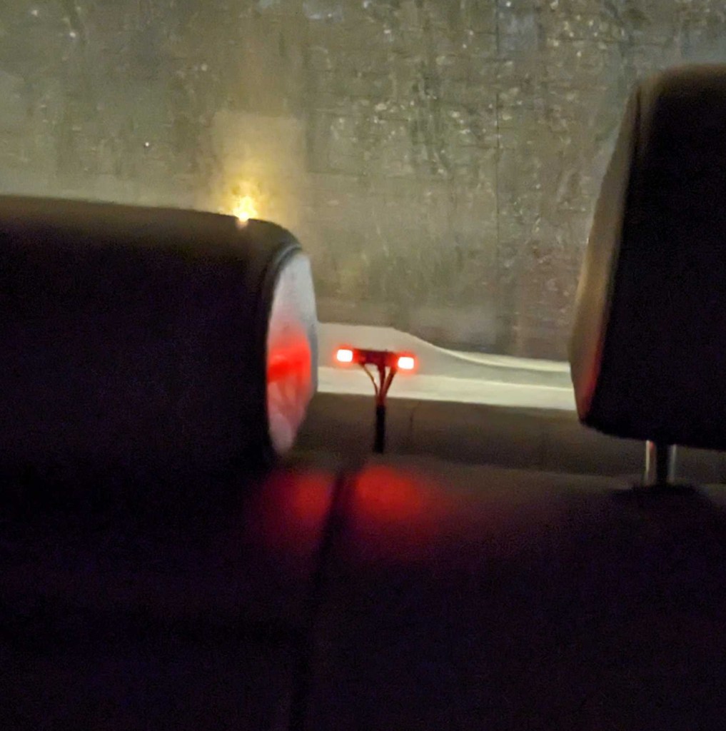
Step 1 was to build and install a lighting monitor module to the car so I could immediately notice any failures with my automotive lighting hacks. The module uses small LED lights to directly show the left turn signal, center brake light, and right turn signal.

Step 2 was to rework the wiring hacks in the car to add a quick-connect junction. My default solution of the manual turn signal would be the “version 0” device and simply consist of two shorted wires.

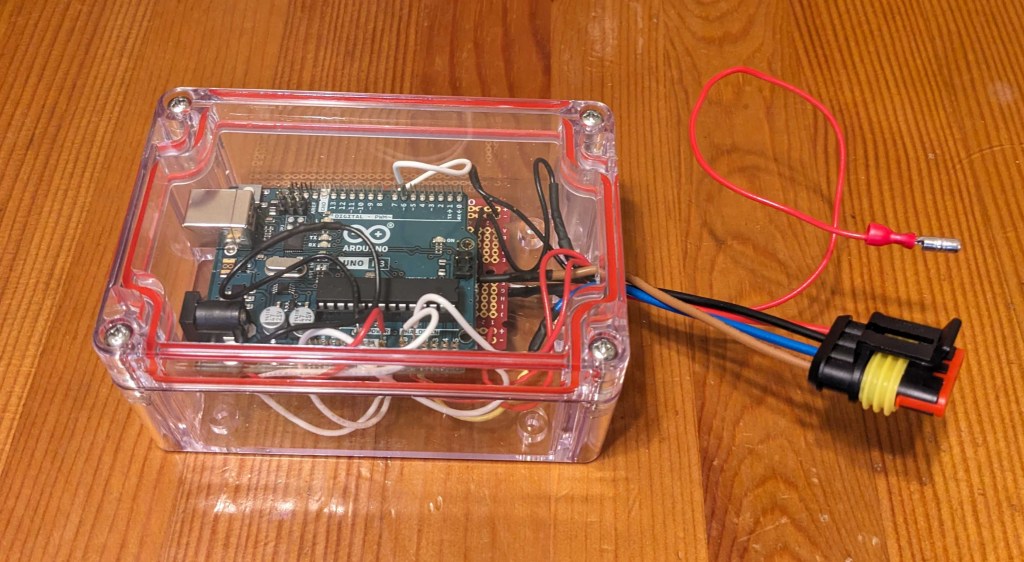
Step 3 is the Arduino device. For this design I’m using a single n-channel MOSFET as a “low side” switch between the load and ground (controlled by pin 6). Then I’m tracking the brake signal with a voltage divider on analog input A0, and tracking the pushbutton grounding with a pullup to +5V on analog input A1. The next step is to write a simple program to control the logic and heavy use of the “millis()” built-in function. Finally we package up everything into a box and plug it in!

Pingback: Turn signal Arduino device – update | Gregory Kimball